
Spinometer Project
The meter component of the project started when I had trouble debugging the pickup. I had a noise problem which I couldn't spot with my oscilloscope for lack of a reliable trigger. Nor could I debug it with print statements because these interfered with the program timing. My solution was to emit program variables on various PWM channels and watch them with my SimpsonVom.
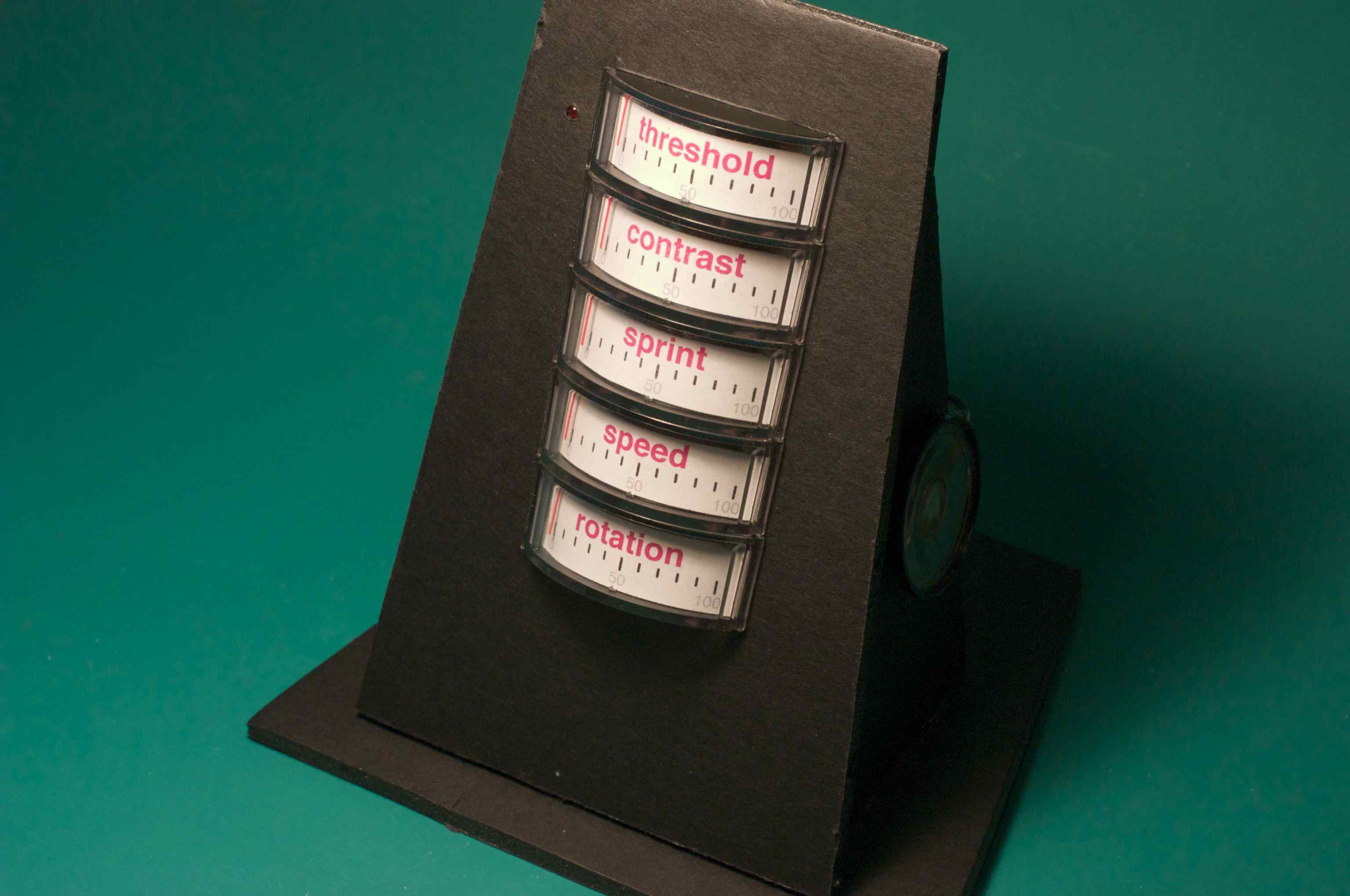
This lead to dedicated meters in a pleasing arrangement with a few extras like a blinking light and a beeping speaker. The meters came from CascadeSurplus.
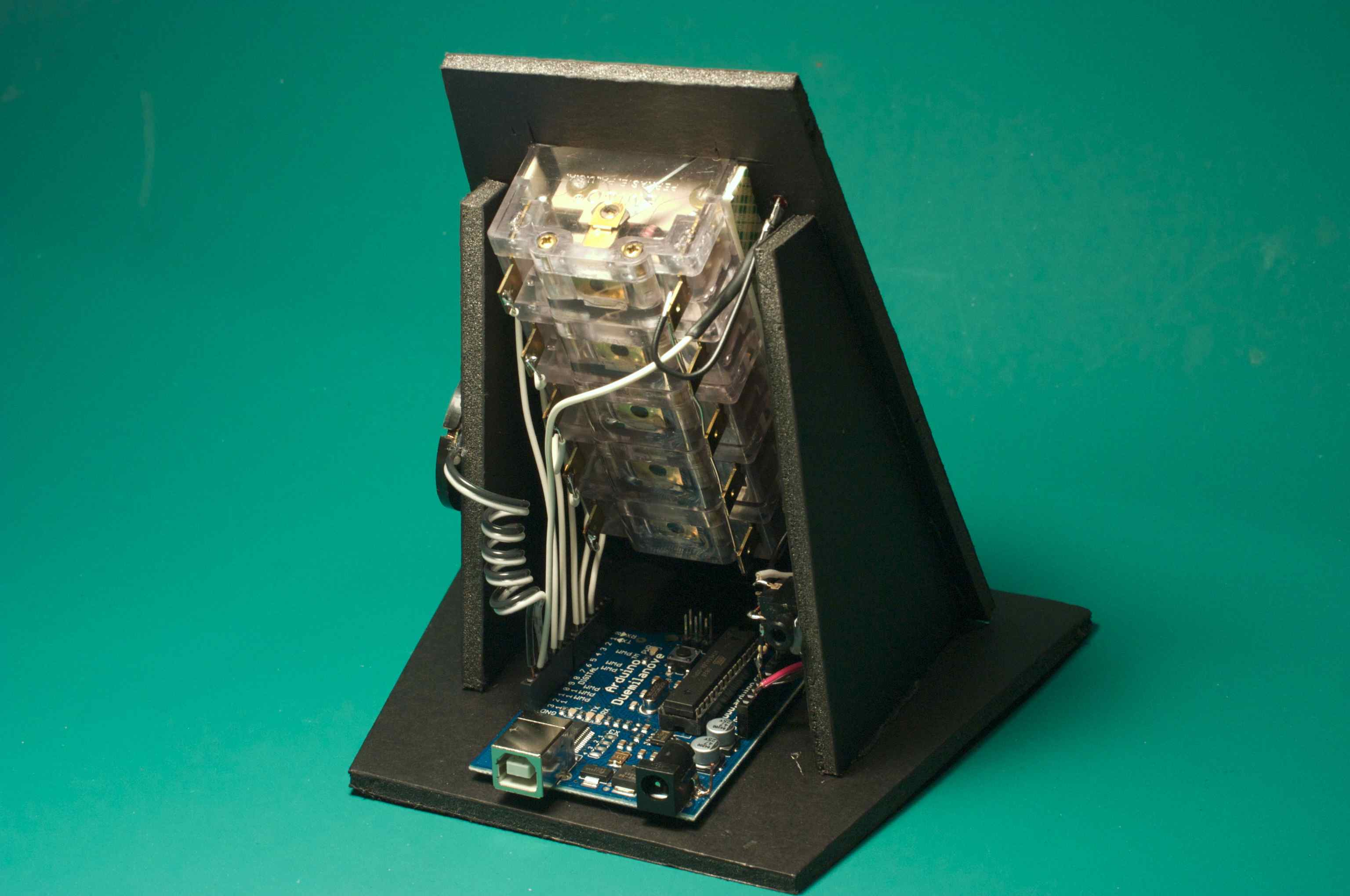
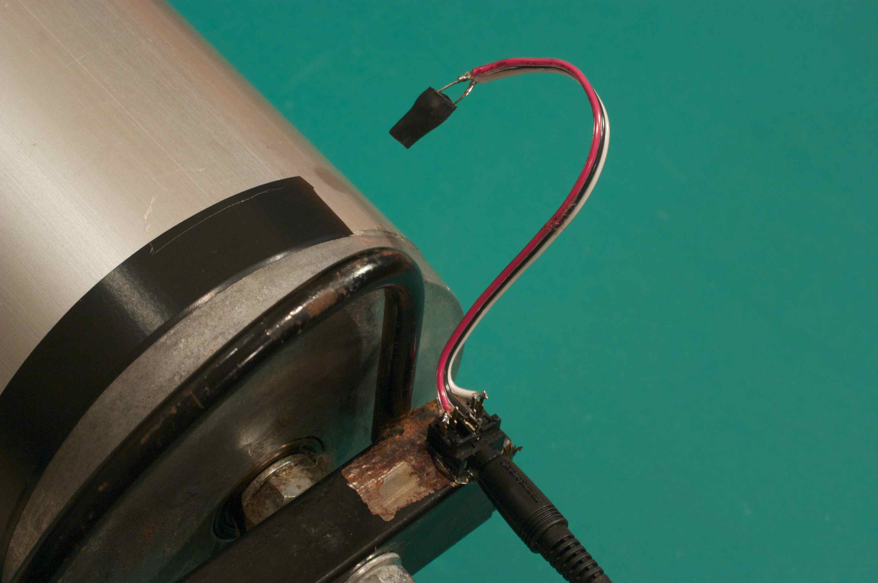
The spinometer connects to the rollers' pickup with 1/8 inch stereo patch cable. I attached the jack to the roller frame with HotMeltGlue and then ran stiff wire to the CdS photo cell which was positioned by bending so as to see light and dark flashes created by black electrical tape wrapped half-way around the roller. A little heat-shrink tubing over the cell blocks unwanted light.
Debugging
I found that I was getting on and off the rollers over and over while debugging. This didn't make for a very interactive development environment. I struggled unsuccessfully to operate my oscilloscope and computer while pedaling. I needed another approach.
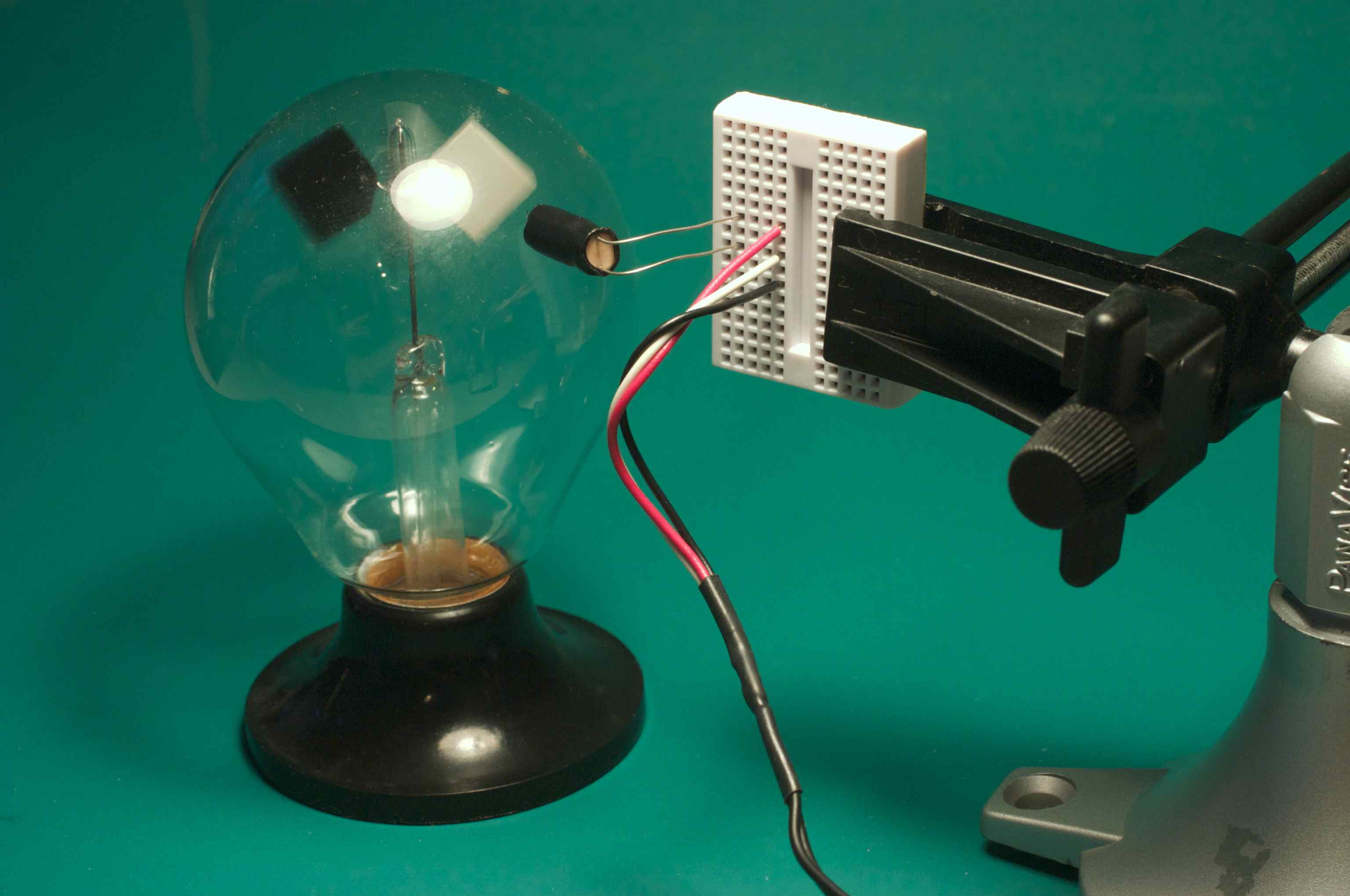
One innovation was to substitute a Radiometer for the roller as it would spin just fine without any effort on my part. I bet you were wondering what a Radiometer was good for. Now you know.
I had used a magnifying lamp to image my Radiometer on a CdS cell before. Here is the sketch I made in 2001 of what I then called a Radiometer Speedometer.
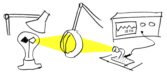
I further improved my spinometer debugging environment by omitting the physical input entirely. I modified the program to simulate the rolling input signal instead. I replaced the single analog input statement:
int sig = analogRead(1);
with a computation that simulates flashing input using the millisecond counter and a modulus function:
int sig = millis()/60%2 ? 100 : 200;
This had the advantage of producing controllable and repeatable stimulus as I tuned the time constants in my filters.
Performance
I read the CdS cell with the analogRead (ADC) command. I filter this with a weighted average so as to get an adaptive threshold. The first two meters monitor this process:
- Threshold -- average ambient light
- Contrast -- variation around the threshold
The third meter measures elapsed time. I use it to challenge myself with sprints, like bell laps at the track.
- Sprint -- five minute repeating timer
The last two meters report the pedaling speed and speed varaiation.
- Speed -- on a scale of zero to thirty.
- Rotation -- full scale means no variation, that is perfect circles.
I report zero variation as a full scale reading and go down from there as variation increases. The ideal for training would be to pin these last two meters for each sprint.
Program
Here is the program as originally written. I've been using my laptop as a battery to power this thing. Someday I will extend this to write data to the laptop so that it can be logged and plotted.
// Spinometer -- Adaptive cycle training meter // (c) 2008 Ward Cunninghamvoid setup () { pinMode(6,OUTPUT); digitalWrite(6,LOW); pinMode(12,OUTPUT); Serial.begin(9600); }
int contrast = 0; long delta; int cycles = 0;
void loop () { trigger(); beep(); }
void trigger () { static float threshold = 150.0; static float level = 150.0; static int min_level, max_level; static boolean prev = false; static long last = 0;
int sig = analogRead(1); //int sig = millis()/60%2 ? 100 : 200; // input simulator
threshold = 0.9999 * threshold + 0.0001 * sig; meter (10, threshold, 1024);
level = 0.9 * level + 0.1 * sig; int i = level; if (i<min_level) min_level=i; if (i>max_level) max_level=i; contrast = max_level - min_level; meter(9, contrast, 250);
boolean curr = level > threshold; digitalWrite(13, curr);
delta = millis() - last;
if (delta > 1000 || (curr != prev && delta > 10)) { prev = curr; if (curr) { last = millis(); measure(); max_level = level; } else { min_level = level; } } }
void measure() { static long sprint = 0; static long minute = 0; static float speed; static float avg_delta = 30; static float rotation = 100; if (contrast > 8) { speed = 840.909090 / delta; avg_delta = avg_delta * 0.9 + delta * 0.1; float min_delta = delta < avg_delta ? delta : avg_delta; float max_delta = delta > avg_delta ? delta : avg_delta; rotation = rotation * 0.9 + (max_delta - min_delta) * 0.1; } else { Serial.println(contrast, DEC); sprint = millis(); minute = millis()+30000L; speed = 0; rotation = 10; } meter(6, (millis()-sprint)%300000, 300000); meter(5, speed, 30.0); meter(3, 10 - rotation, 10); if (millis()>minute) { cycles = 150; minute = millis()+30000L; } }
void beep () { static boolean toggle = LOW; if (cycles>0) { toggle = !toggle; digitalWrite(12, toggle); cycles--; } }
void meter(int pin, float value, float scale) { float volts = value * 1.2 / scale; // scale to meter full-scale volts volts = volts > 1.3 ? 1.3 : volts < 0 ? 0: volts; int pwm = volts * 255 / 4.82; // scale to proprtion of vcc analogWrite(pin, pwm); }
Update
My car was stolen 1/09 with my bike and rollers from my office the day I was taking the Spinometer to Dorkbot to show it off. The car and rollers were recovered five months later. Now, after a year of bicycle commuting I am again interested in indoor training and have revived the project.
My first modification was to up the speed scale, 30.0 => 50.0, reflecting a year of training. This places 25 MPH mid scale. 25 seems to be the boundary for sprinting given my current conditioning. I've spun it up to 40 MPH, which was an uncomfortably fast and uncoordinated cadence on the rollers.
I share my source code updates to this project at https://github.com/WardCunningham/Spinometer
Return to WelcomeVisitors